
There are many interviews about the Wi-Fi 7 (IEEE 802.11BE) capabilities about the revolution of the wireless experience. It’s not hype. The key feature that provides this transformation impact is surgery with multiple lines (MLO). The mandate and defining the 802.11BE component, the MLO allow multi-line equipment (BLD) to operate across several fequecy bands at the same time, includes 2.4 GHz, 5 GHz and 6 GHz.
Access point (AP) and non-AP BLD learn each other to parameters and capabilities through information elements with multiple lines replaced in frames such as lighthouses and request/Association’s response. In this blog, the impact of the illustration was on wireless connection and shows how it works in current transmission/reception mode (STR).
How does Multi-Link (Mlo) an increase in wireless connection?
Mlo brings significant advantages for different use of boxes. Key improvements include:
- The simultaneous uses multiple belts. MLDS can transmit (TX) and receive (RX) data in more than one band simultaneously. This is useful in the vicinity with severe overload because it has interference on any individual zone.
- Improved permeability. Mlo uses the combined capacity of multiple channels across different belts to allow higher aggregated permeability. This makes the Wi-Fi 7 ideal for bandwidth applications such as video streaming, virtual reality and online gaming.
- Reduced latency. Unloading traffic on multiple channels. This is particularly useful in playing, video conferencing or other applications that require real -time communication.
- Better distribution and robustness. If one belt (for example, 2.4 GHz) experiences overload, then the stations (STA) Mels can easily switch to a less cosmetic band (for example 6 GHz) without dropping the connection. This is very useful in premises with busy operation of the radio frequency (RF) such as stadiums, apartments and offices.
Type of operations of the operation of the Mlo
Wi-Fi 7 defines several modes of individual and multi-radio Mlo, with their support based on their appropriate hardware capabilities. Different software threshold values - such as zone width requirements, band preferences, RF overload and QoS – will affect and lead to the selection of station operating mode.
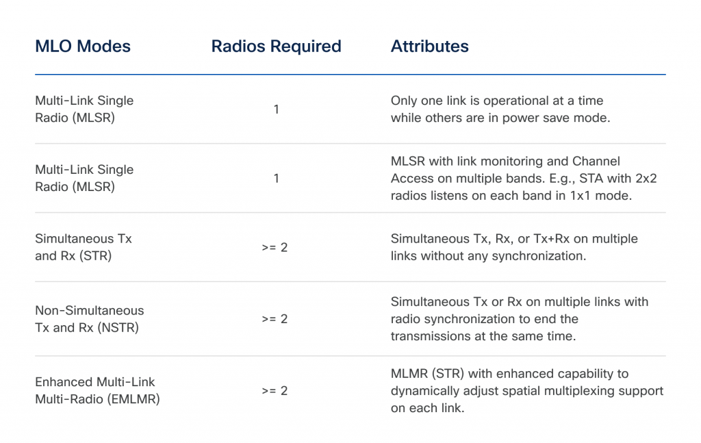
Between these modes, the MLSR must be supported by all AP and NON AP MLDDS. Support for EMLSR and STR modes is an AP MLDS mandate, optional for bills without AP (station). Str is currently incorporated by most retailers, which makes this fashion an excellent starting point for autopsy.
Str mlo mode in action
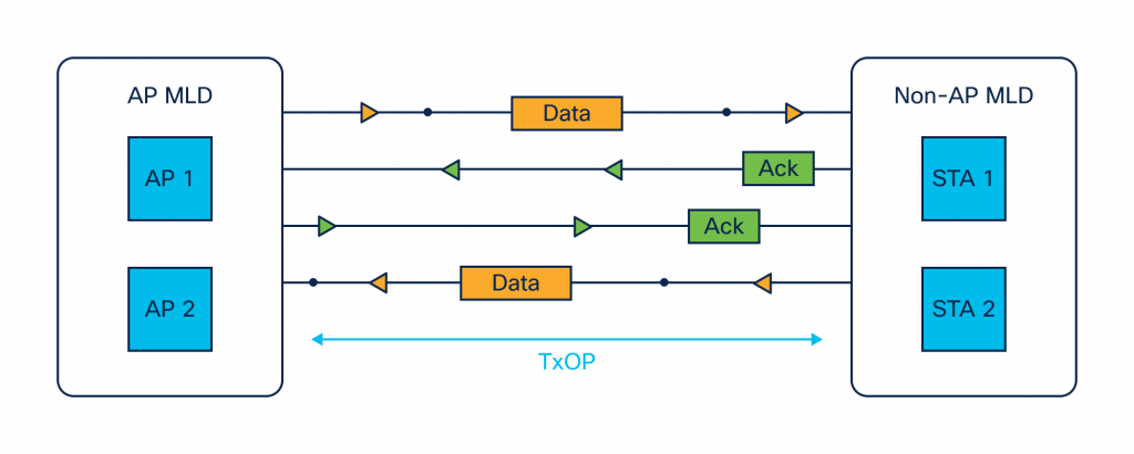
During the STR surgery, each link can be used for the TX or RX data units of the competing physical layer (PPDU) without any synchronization. Figure 2 illustrates an example where AP BLD and NON-AP MLD work on steam Str. Both cash registers for access to the wireless medium and engage in subsequent frames on these links.
After AP BLD and NON-AP MLD complete the settings for multiple links to successfully create link 1 and link 2 as allowed links can receive AP 2 data frames from ST 2 on link 2. TXOP), data frame transfer to ST 1 on link 1.
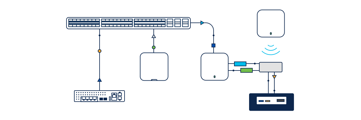
We will also carry out a laboratory test using the CISCO CW9178i AP running on the Catalyst 9800 Wireless LAN controller (WLC) to demonstrate str.
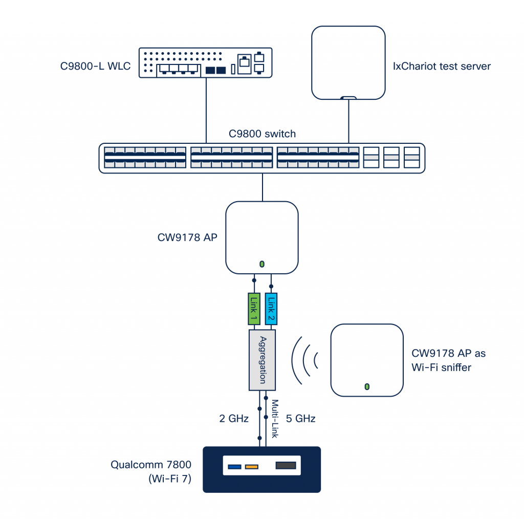
The test point (APUT) is configured to work at 2.4 GHz (20 MHz) and 5 GHz (40 MHz) bandwidth with WPA3-SAE WLAN. In the first step of the test, Wi-Fi 7/802.11be/Mlo is allowed on both belts. We use a STR/MLMR station based on the Qualcomm 7800, while the AP CW9178I serves as a sniffer capture data across multiple belts and Wi-Fi decoding.
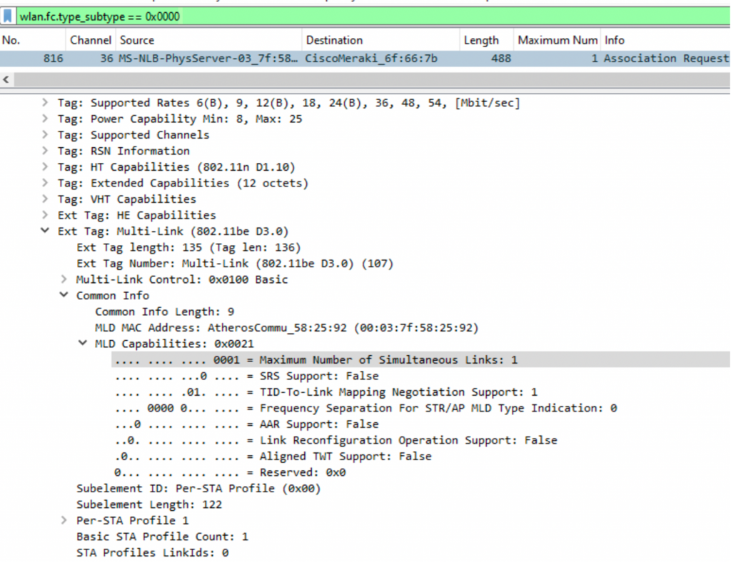
Let’s further assign Stat and check the details of WLC and WireShark capabilities. More elements are exchanged during the association process: Information elements were to connect 5 GHz associations and information elements of “per-Sta” profiles containing details about the connection without association (2 GHz).
WLC identifies hundreds as STA unable to do if the “maximum number of simultaneous links” in the information element of the ML application for the association is non -zero. This shows the number of radios used by its association. See Figure 4 below for the corresponding WireShark capture.
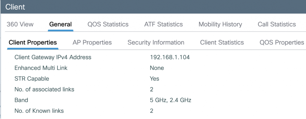
The 9800 WLC catalyst provides a clear display of one hundred 802.11Be capacity, including bills of links with slots and belts, MOLO MODE (STR/EMLSR) and TX/RX RF and data statistics for each belt. Equivalent CLI commands are also available, although they are not included in this blog.

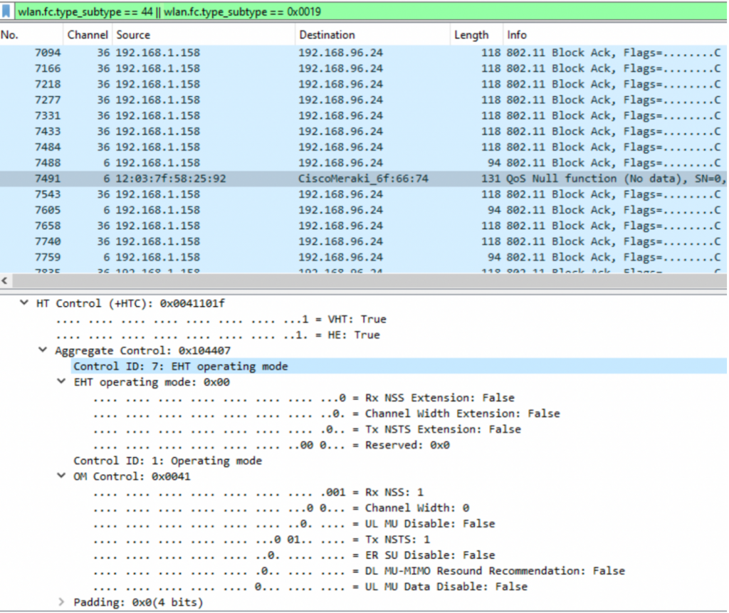
Now that the STA has joined the 5G band with a link to the booth 5G and 2G bands, we will start operation for one minute to verify the operation of the STR. Using the ixchariot server we start downlink Downlink UDP Downwidth. Initially, the operation will only flow on the 5G band because it is the only Active Association link. However, it will soon assess the need for a secondary connection to achieve a higher bandwidth. Then the QoS null data frame will have a link. AP confirms this application and allows current data transfer across both bands.
Figure 6 shows the sequence starting with the data on channel 36, followed by the QoS null data frame on channel 6 and closes with the current data transfer to channel 6 and channel 36.
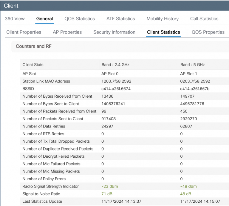
The Catalyst 9800 WLC offers an understanding view of the client’s performance on each link MLO, while the monitors provide detailed TX/RX data along with RF statistics.
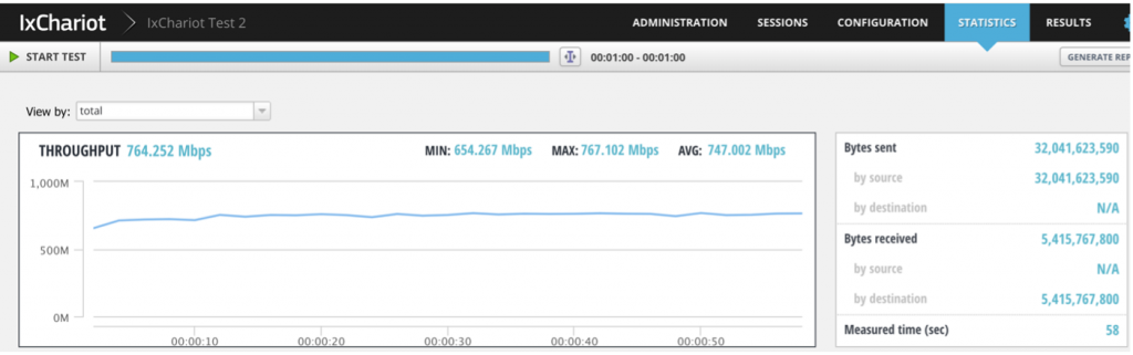
After one -minute operation, the average measured permeability is 747 Mbps, as shown in Figure 8.
To provide the comparison, the test was repeated under the same conditions, but with 802.11be/Mlo deactivated, instead run in 802.11ax mode. The average permeability was 506 Mbps.
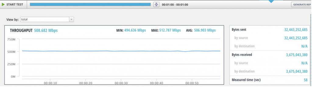
The table below summarizes the comparison of the permeability among customers. The impact is truly transformative: Wi-Fi 7 s Str Mlo significantly overcomes Wi-Fi 6, which provides an increase in permeability by 47% along with a more efficient spectrum.

CW9178I, CW9176i and CW9176D1 APS, along with 9800 wireless controllers, will fully support Wi-Fi 7 from iOS x 17.15.2 Further.
Share: